1. Introduction
With the rapid development of modern manufacturing technology, aerospace engineering, and automotive industry, the requirements for mechanical transmission components are constantly upgrading—lightweight, high efficiency, high precision, and integration have become the core development trends. Traditional solid shafts, which rely on increasing cross-sectional area to meet load-bearing and transmission needs, have the defects of heavy weight, high material consumption, and poor structural flexibility, which can no longer adapt to the development needs of high-speed, lightweight, and high-performance equipment. Hollow shafts, through the optimization of structural design, realize the balance between weight reduction and performance improvement, solving the pain points of solid shafts in lightweight equipment and high-speed transmission scenarios.
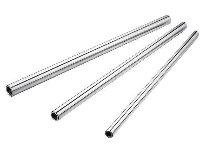
A hollow shaft is a cylindrical transmission component with a hollow inner cavity, whose core advantage lies in the high specific stiffness (stiffness per unit weight)—under the same weight condition, the stiffness of a hollow shaft is significantly higher than that of a solid shaft; under the same load-bearing condition, the weight of a hollow shaft is much lower than that of a solid shaft, which can effectively reduce the inertial force of high-speed rotation, reduce energy consumption, and extend the service life of bearings and other matching components. The design quality of hollow shafts directly determines the transmission accuracy, load-bearing capacity, and operational stability of the entire mechanical system—unreasonable design will lead to problems such as insufficient stiffness, fatigue fracture, and vibration, which will affect the normal operation of the equipment.
At present, there are still prominent problems in the practical design and application of hollow shafts, such as unreasonable wall thickness design, improper material selection, imprecise precision control, and mismatched connection modes, which restrict the exertion of their performance advantages. Therefore, it is particularly important to systematically analyze the key design points of hollow shafts and clarify their core application scenarios, so as to provide a scientific basis for the design and application of hollow shafts.
This paper takes
hollow shafts as the research object, focuses on the key design points, analyzes their design principles and technical requirements, classifies and discusses the core application scenarios, and verifies the application effect through practical cases. The research results can help relevant practitioners master the core knowledge of hollow shaft design and application, avoid common design mistakes, and promote the wide application of hollow shafts in high-performance mechanical systems.
2. Key Design Points of Hollow Shafts
The design of hollow shafts is a systematic project that needs to comprehensively consider load-bearing requirements, transmission performance, processing technology, and application scenarios. The key design points include structural design, material selection, wall thickness determination, precision control, and connection mode design, which are mutually restrictive and complementary, and together determine the overall performance of hollow shafts.
2.1 Structural Design
The structural design of hollow shafts is the foundation of their performance, which mainly includes the design of cross-sectional shape, inner cavity structure, and end structure. The design should be based on the load type, transmission mode, and installation space, and realize the balance between performance and manufacturability.
2.1.1 Cross-Sectional Shape Design
The cross-sectional shape of hollow shafts directly affects their load-bearing capacity, stiffness, and transmission efficiency. The most commonly used cross-sectional shape is circular, which has the advantages of uniform stress distribution, simple processing, and good rotational balance, and is suitable for most transmission scenarios (such as high-speed shafts, transmission shafts). In addition, according to specific application requirements, special cross-sectional shapes can be designed:
- Elliptical Cross-Section: Suitable for scenarios with limited installation space and uneven load distribution, which can adapt to the spatial layout while ensuring load-bearing capacity.
- Polygonal Cross-Section: (Such as square, hexagonal) Suitable for non-rotational transmission or scenarios requiring torque transmission without key connection, which has good anti-slip performance.
- Stepped Cross-Section: Suitable for hollow shafts with different load requirements at different sections, which can reduce weight while ensuring local stiffness and load-bearing capacity.
It should be noted that the cross-sectional shape should be as regular as possible to ensure uniform stress distribution and reduce processing difficulty. For high-speed rotating hollow shafts, the circular cross-section is preferred to avoid unbalanced centrifugal force caused by irregular shape.
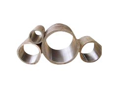
2.1.2 Inner Cavity Structure Design
The inner cavity structure of hollow shafts is closely related to their weight reduction effect, stiffness, and functional integration. Common inner cavity structures include:
- Uniform Inner Cavity: The inner diameter is consistent along the axial direction, which is simple to process and suitable for most general transmission scenarios. The weight reduction effect is determined by the ratio of inner diameter to outer diameter (hollow ratio).
- Tapered Inner Cavity: The inner diameter gradually changes along the axial direction, which is suitable for hollow shafts with changing load requirements, and can realize the matching between local stiffness and load distribution.
- Multi-Cavity Structure: The inner cavity is divided into multiple independent cavities, which can improve the stiffness and stability of the hollow shaft, and is suitable for high-precision and high-stiffness transmission scenarios (such as aerospace equipment shafts).
- Functional Inner Cavity: The inner cavity is designed as an oil passage, gas passage, or wire passage, realizing the integration of transmission and functional integration, which is suitable for equipment with limited installation space (such as automotive powertrains, hydraulic systems).
2.1.3 End Structure Design
The end structure of hollow shafts is mainly used for connection with other components (such as gears, couplings, bearings), and its design directly affects the connection reliability and transmission efficiency. Common end structures include:
- Flange Connection End: The end is designed as a flange, which is connected with other components through bolts, with high connection strength and good centering performance, suitable for heavy-load transmission scenarios.
- Threaded Connection End: The end is processed with internal or external threads, which is simple to disassemble and assemble, suitable for light-load and medium-load transmission scenarios.
- Keyway Connection End: The end is processed with a keyway, which is connected with other components through a key, with simple structure and reliable transmission, suitable for torque transmission scenarios.
- Spline Connection End: The end is processed with splines (rectangular splines, involute splines), which has high transmission accuracy, large load-bearing capacity, and good centering performance, suitable for high-precision and heavy-load transmission scenarios.
2.2 Material Selection
The material of hollow shafts directly determines their strength, stiffness, fatigue resistance, and corrosion resistance. The selection of materials should be based on the working conditions (load type, working temperature, environmental conditions) and performance requirements (load-bearing capacity, transmission accuracy, service life), and follow the principle of ""performance matching, cost optimization"".
Common materials for hollow shafts include:
- Alloy Steel: It is the most commonly used material for hollow shafts, with the advantages of high strength, good fatigue resistance, and excellent machinability. ① 40Cr Alloy Steel: Suitable for medium and heavy-load transmission scenarios (such as industrial machinery transmission shafts), after quenching and tempering treatment, its tensile strength can reach ≥980MPa, and its hardness can reach HRC28~32. ② 20CrMnTi Alloy Steel: Suitable for high-speed, heavy-load, and impact-load transmission scenarios (such as automotive gear shafts), after carburizing and quenching treatment, the surface hardness can reach HRC58~62, with excellent wear resistance and fatigue resistance. ③ 12CrNi3A Alloy Steel: Suitable for high-precision, high-stiffness, and high-fatigue-resistance transmission scenarios (such as aerospace equipment shafts), with high strength, good toughness, and excellent fatigue resistance.
- Stainless Steel: Suitable for corrosive environments (such as marine equipment, chemical machinery) and high-precision scenarios. ① 316L Stainless Steel: Has excellent corrosion resistance, resistant to salt spray, strong acid, and strong alkali, suitable for hollow shafts in harsh corrosive environments. ② 17-4PH Stainless Steel: A precipitation-hardening stainless steel with high strength (tensile strength ≥1030MPa) and good corrosion resistance, suitable for high-precision and high-corrosion transmission scenarios.
- Lightweight Materials: Suitable for lightweight equipment (such as aerospace, automotive) to further reduce weight. ① Titanium Alloy (TC4): Lightweight (density 4.51g/cm³), high strength, and excellent corrosion resistance, suitable for high-end aerospace and automotive hollow shafts. ② Carbon Fiber Composites: Has the advantages of lightweight, high specific stiffness, and high specific strength, suitable for ultra-lightweight and high-precision transmission scenarios (such as aircraft engine shafts), but the cost is high and the machinability is poor.
- Carbon Steel: Suitable for light-load and low-cost transmission scenarios (such as ordinary industrial machinery). 45# Carbon Steel: After quenching and tempering treatment, it has good strength and machinability, but its fatigue resistance and corrosion resistance are worse than those of alloy steel.
2.3 Wall Thickness Determination
The wall thickness of hollow shafts is a key parameter that balances weight reduction, load-bearing capacity, and stiffness. Too thin wall thickness will lead to insufficient stiffness, poor load-bearing capacity, and easy deformation or fatigue fracture; too thick wall thickness will reduce the weight reduction effect, increase material consumption and processing cost. The determination of wall thickness should be based on the load calculation, stiffness calculation, and processing technology, and the following principles should be followed:
2.3.1 Load-Bearing Capacity Calculation
The wall thickness of hollow shafts should first meet the load-bearing requirements, including tensile load, compressive load, torque load, and bending load. The key calculation formulas are as follows:
- Torque Load Calculation: The allowable torque of the hollow shaft is calculated according to the shear strength formula: T ≤ (π/16) × τ × (D⁴ - d⁴)/D, where T is the torque (N·m), τ is the allowable shear stress of the material (Pa), D is the outer diameter of the hollow shaft (m), and d is the inner diameter of the hollow shaft (m).
- Bending Load Calculation: The allowable bending moment of the hollow shaft is calculated according to the bending strength formula: M ≤ (π/32) × σ_b × (D⁴ - d⁴)/D, where M is the bending moment (N·m), σ_b is the allowable bending strength of the material (Pa).
Based on the above calculations, the initial wall thickness is determined, and a safety factor (usually 1.2~1.5) is added to ensure the load-bearing safety.
2.3.2 Stiffness Calculation
The stiffness of hollow shafts is crucial to the transmission accuracy, especially for high-speed and high-precision transmission scenarios. The stiffness includes bending stiffness and torsional stiffness:
- Bending Stiffness: The bending stiffness of the hollow shaft is calculated according to the formula: EI, where E is the elastic modulus of the material (Pa), and I is the moment of inertia of the cross-section (m⁴). The moment of inertia I = π(D⁴ - d⁴)/64, which is positively related to the wall thickness.
- Torsional Stiffness: The torsional stiffness of the hollow shaft is calculated according to the formula: GIp, where G is the shear modulus of the material (Pa), and Ip is the polar moment of inertia of the cross-section (m⁴). The polar moment of inertia Ip = π(D⁴ - d⁴)/32, which is also positively related to the wall thickness.
The wall thickness should be adjusted according to the stiffness requirements to ensure that the deformation of the hollow shaft under load is within the allowable range (usually the bending deformation ≤0.001mm/m, the torsional deformation ≤0.1rad/m).
2.3.3 Hollow Ratio Control
The hollow ratio (λ = d/D, where d is the inner diameter, D is the outer diameter) is an important indicator to measure the weight reduction effect and performance of hollow shafts. The reasonable hollow ratio is usually 0.5~0.8:
- When λ < 0.5: The weight reduction effect is not obvious, and the material utilization rate is low, which is not suitable for lightweight design.
- When 0.5 ≤ λ ≤ 0.8: The balance between weight reduction and performance is achieved, and the specific stiffness is the highest, which is suitable for most application scenarios.
- When λ > 0.8: The wall thickness is too thin, the stiffness and load-bearing capacity are significantly reduced, and the processing difficulty is increased, which is only suitable for light-load and ultra-lightweight scenarios.
2.4 Precision Control
The precision of hollow shafts directly affects the transmission accuracy, centering performance, and matching performance with other components. The key precision indicators include dimensional precision, shape precision, position precision, and surface quality, which should be controlled according to the application requirements.
- Dimensional Precision: The outer diameter tolerance is usually controlled within IT5~IT7, the inner diameter tolerance within IT6~IT8, and the wall thickness tolerance within ±0.05~±0.1mm. For high-precision transmission scenarios (such as aerospace equipment), the outer diameter tolerance can be controlled within IT4~IT5.
- Shape Precision: The straightness deviation of the hollow shaft is ≤0.002mm/m, the roundness deviation of the cross-section is ≤0.001mm, and the cylindricity deviation is ≤0.002mm. For high-speed rotating hollow shafts, the shape precision should be further improved to avoid unbalanced centrifugal force.
- Position Precision: The coaxiality between the inner and outer surfaces is ≤0.01mm/m, the perpendicularity between the end face and the axis is ≤0.005mm/m, and the position tolerance of the keyway, spline, and other structures is ≤0.01mm.
- Surface Quality: The surface roughness of the outer and inner surfaces is Ra≤0.4μm, and the surface should be free of scratches, wear, corrosion, and other defects. For high-speed and high-precision scenarios, the surface roughness can be controlled within Ra≤0.1μm to reduce friction and improve transmission efficiency.
To ensure the precision of hollow shafts, advanced processing technologies such as precision turning, grinding, honing, and boring should be adopted, and strict quality inspection should be carried out during the processing process.
2.5 Connection Mode Design
The connection mode of hollow shafts with other components (gears, couplings, bearings) directly affects the connection reliability, transmission efficiency, and maintainability. The design of the connection mode should be based on the load type, transmission accuracy, and disassembly requirements, and the following common connection modes can be selected:
- Key Connection: Simple structure, reliable transmission, easy processing, suitable for torque transmission scenarios with medium load and general precision. Common key types include flat keys, semicircular keys, and spline keys. The keyway should be processed with high precision to avoid stress concentration.
- Spline Connection: High transmission accuracy, large load-bearing capacity, good centering performance, suitable for high-precision, heavy-load, and high-speed transmission scenarios. Common spline types include rectangular splines and involute splines. The spline tooth profile should be accurately processed to ensure uniform stress distribution.
- Flange Connection: High connection strength, good centering performance, suitable for heavy-load and large-torque transmission scenarios. The flange surface should be flat and smooth, and the bolt connection should be evenly stressed to avoid uneven force caused by flange deformation.
- Interference Fit Connection: No additional connection components, compact structure, high transmission accuracy, suitable for high-precision and high-speed transmission scenarios. The interference amount should be reasonably controlled to avoid excessive interference leading to shaft deformation or insufficient interference leading to slippage.
- Threaded Connection: Simple to disassemble and assemble, suitable for light-load and medium-load transmission scenarios. The thread should be processed with high precision, and a locking device (such as a lock nut, cotter pin) should be added to prevent loosening during operation.
3. Core Application Scenarios Analysis of Hollow Shafts
Hollow shafts, with their advantages of lightweight, high specific stiffness, and functional integration, are widely used in various fields. According to the working conditions and performance requirements, the core application scenarios can be divided into high-speed transmission systems, aerospace equipment, automotive engineering, industrial machinery, and precision equipment, and the matching design characteristics of each scenario are analyzed in detail as follows:
3.1 High-Speed Transmission Systems
High-speed transmission systems (such as high-speed motors, precision machine tool spindles, and centrifugal pumps) have high requirements for the rotational speed, transmission accuracy, and dynamic balance of shafts. Hollow shafts are the preferred components in such scenarios, and their design characteristics are:
- Lightweight design: The hollow structure reduces the weight of the shaft, thereby reducing the inertial force of high-speed rotation, reducing vibration and noise, and improving the dynamic balance performance. The hollow ratio is usually 0.6~0.7 to achieve the balance between weight reduction and stiffness.
- High precision: The dimensional precision, shape precision, and position precision are strictly controlled (outer diameter tolerance IT4~IT5, straightness ≤0.001mm/m) to ensure the transmission accuracy and dynamic balance.
- High fatigue resistance: The material is usually high-strength alloy steel (such as 20CrMnTi, 12CrNi3A) with good fatigue resistance, which can withstand the alternating stress caused by high-speed rotation.
Application examples: Precision machine tool spindles adopt hollow shafts to reduce rotational inertia, improve the response speed and processing accuracy of the spindle; high-speed motors use hollow shafts to reduce energy consumption and improve the service life of bearings.
3.2 Aerospace Equipment
Aerospace equipment (such as aircraft engines, spacecraft transmission systems) has strict requirements for lightweight, high strength, high precision, and corrosion resistance. Hollow shafts are widely used in such equipment, and their design characteristics are:
- Ultra-lightweight design: Adopt lightweight materials (titanium alloy, carbon fiber composites) and high hollow ratio (0.7~0.8) to reduce the overall weight of the equipment, which is crucial for improving the range and load capacity of aerospace equipment.
- High strength and stiffness: The material has high specific strength and specific stiffness to withstand the high load and harsh working environment (high temperature, high pressure, vibration) in aerospace.
- Functional integration: The inner cavity of the hollow shaft is designed as an oil passage, gas passage, or wire passage, realizing the integration of transmission and functional integration, saving installation space.
Application examples: Aircraft engine shafts adopt titanium alloy hollow shafts to reduce weight while ensuring high strength and high temperature resistance; spacecraft transmission systems use carbon fiber composite hollow shafts to achieve ultra-lightweight and high precision.
3.3 Automotive Engineering
Automotive engineering (especially new energy vehicles) has increasingly high requirements for lightweight, energy conservation, and emission reduction. Hollow shafts are widely used in automotive powertrains, drive shafts, and steering systems, and their design characteristics are:
- Lightweight design: The hollow structure reduces the weight of the shaft, thereby reducing the overall weight of the vehicle, improving fuel efficiency (for traditional fuel vehicles) or battery life (for new energy vehicles). The hollow ratio is usually 0.5~0.6.
- High load-bearing capacity: The material is usually alloy steel (40Cr, 20CrMnTi) with good strength and fatigue resistance, which can withstand the torque and impact load during vehicle operation.
- Good manufacturability: The structure is simple, the processing cost is low, and it is suitable for mass production.
Application examples: Automotive drive shafts adopt hollow shafts to reduce weight and improve transmission efficiency; new energy vehicle motor shafts use hollow shafts to reduce rotational inertia and improve the dynamic performance of the vehicle.
3.4 Industrial Machinery
Industrial machinery (such as metallurgical equipment, mining machinery, and hydraulic machinery) has high requirements for load-bearing capacity, durability, and reliability. Hollow shafts are used in such equipment to achieve weight reduction and cost saving while ensuring performance, and their design characteristics are:
- High load-bearing capacity: The wall thickness is reasonably designed, and the material is high-strength alloy steel to withstand heavy load and impact load.
- Good corrosion resistance: For harsh working environments (such as wet, dusty, corrosive), the surface of the hollow shaft is treated with chrome plating, nitriding, or other anti-corrosion treatments to extend the service life.
- Simple structure and easy maintenance: The connection mode is simple, and the disassembly and maintenance are convenient, which is suitable for the harsh working environment of industrial machinery.
Application examples: Metallurgical equipment rollers adopt hollow shafts to reduce weight and improve heat dissipation performance; mining machinery transmission shafts use hollow shafts to withstand heavy load and impact load.
3.5 Precision Equipment
Precision equipment (such as precision measuring instruments, medical equipment, and robotics) has high requirements for transmission accuracy, stability, and miniaturization. Hollow shafts are used in such equipment to achieve miniaturization and high precision, and their design characteristics are:
- High precision: The dimensional precision, shape precision, and position precision are strictly controlled to ensure the transmission accuracy and stability of the equipment.
- Miniaturized design: The hollow structure saves installation space, which is suitable for the miniaturization development trend of precision equipment.
- Good surface quality: The surface roughness is low (Ra≤0.1μm) to reduce friction and improve the transmission accuracy.
Application examples: Precision measuring instrument shafts adopt hollow shafts to ensure high transmission accuracy; medical equipment (such as surgical robots) use hollow shafts to achieve miniaturization and high precision.
4. Practical Application Cases and Effect Analysis
To verify the design rationality and application value of hollow shafts, this section selects typical application cases in high-speed transmission systems and automotive engineering, and analyzes the performance improvement and economic benefits brought by the application of hollow shafts.
4.1 Case 1: Hollow Shaft Application in High-Speed Precision Machine Tool Spindles
A precision machine tool manufacturer produces high-speed precision machining centers, and the original spindle adopts solid 40Cr alloy steel shafts with a diameter of 80mm. Due to the heavy weight of the solid shaft (weight 32kg), the rotational inertia is large, which leads to problems such as low spindle response speed, large vibration, and reduced processing accuracy (processing error ≥0.01mm). In addition, the material consumption is large, and the processing cost is high.
The manufacturer optimized the spindle design: ① Adopted hollow shaft structure, selected 20CrMnTi alloy steel as the material, outer diameter 80mm, inner diameter 56mm (hollow ratio 0.7), weight reduced to 18kg (weight reduction rate 43.75%); ② Adopted precision grinding and honing technology to control the outer diameter tolerance within IT4, straightness ≤0.001mm/m, surface roughness Ra≤0.1μm; ③ Adopted spline connection mode to ensure high transmission accuracy and centering performance.
After the improvement, the spindle response speed is increased by 30%, the vibration amplitude is reduced by 50%, the processing error is reduced to ≤0.005mm, and the processing accuracy is significantly improved. At the same time, the material consumption is reduced by 43.75%, the processing cost is reduced by 25%, and the service life of the spindle is extended by 40%, achieving significant economic and technical benefits.
4.2 Case 2: Hollow Shaft Application in New Energy Vehicle Drive Shafts
A new energy vehicle manufacturer produces pure electric vehicles, and the original drive shaft adopts solid 45# carbon steel shafts with a diameter of 60mm. Due to the heavy weight of the solid shaft (weight 15kg), the overall weight of the vehicle is increased, which leads to a reduction in battery life (reduced by 8%). In addition, the fatigue resistance of the solid shaft is poor, and the service life is only 120,000 kilometers.
The manufacturer optimized the drive shaft design: ① Adopted hollow shaft structure, selected 40Cr alloy steel as the material, outer diameter 60mm, inner diameter 36mm (hollow ratio 0.6), weight reduced to 9.6kg (weight reduction rate 36%); ② After quenching and tempering treatment, the tensile strength reached ≥1000MPa, and the fatigue resistance was significantly improved; ③ Adopted flange connection mode to ensure connection reliability and transmission efficiency.
After the improvement, the overall weight of the vehicle is reduced by 5.4kg, the battery life is increased by 10%, the service life of the drive shaft is extended to 200,000 kilometers, and the maintenance cost is reduced by 30%. The operational stability of the vehicle is also significantly improved, which is well received by the market.
5. Future Development Trends of Hollow Shafts
With the continuous development of new material technology, precision machining technology, and intelligent manufacturing technology, hollow shafts will develop towards high precision, lightweight, functional integration, and intelligence, further improving their performance and expanding their application scope.
- Ultra-Lightweight and High-Strength Development: Develop new high-performance lightweight materials (such as carbon fiber composites, high-strength titanium alloy) and optimize the structural design (such as bionic structure, multi-cavity structure) to further reduce weight while improving strength and stiffness, adapting to the lightweight development needs of aerospace, automotive, and other fields.
- High-Precision and Ultra-Precision Processing: Adopt advanced processing technologies such as laser machining, electron beam machining, and ion beam machining to improve the dimensional precision, shape precision, and surface quality of hollow shafts. The outer diameter tolerance can reach IT3~IT4, and the surface roughness can reach Ra≤0.01μm, meeting the high-precision requirements of aerospace and precision equipment.
- Functional Integration and Multi-Parameter Design: Integrate multiple functions (transmission, oil passage, gas passage, sensor installation) into the hollow shaft, realizing the integration of structure and function. At the same time, adopt multi-parameter optimization design (considering load, stiffness, weight, processing cost, etc.) to improve the comprehensive performance of hollow shafts.
- Intelligent Monitoring and Life Prediction: Integrate intelligent technologies (such as IoT, sensors, AI) into hollow shafts, install sensors on the shaft body to realize real-time monitoring of stress, temperature, vibration, and other parameters. Through AI algorithms, predict the service life of hollow shafts, realize fault early warning, and reduce manual maintenance.
- Green and Low-Carbon Manufacturing: Adopt environmentally friendly materials and processing technologies, reduce energy consumption and environmental pollution during the manufacturing process. Optimize the material utilization rate, reduce material waste, and realize the green and low-carbon development of hollow shaft manufacturing.
6. Conclusion
Hollow shafts, as a lightweight and high-performance mechanical transmission component, have unique advantages in weight reduction, high specific stiffness, material saving, and functional integration, and have become the core components of high-speed, lightweight, and high-performance mechanical systems. The key design points of hollow shafts, including structural design, material selection, wall thickness determination, precision control, and connection mode design, are mutually restrictive and complementary, and the scientific design of these points is the key to ensuring the performance and reliability of hollow shafts.
The core application scenarios of hollow shafts cover high-speed transmission systems, aerospace equipment, automotive engineering, industrial machinery, and precision equipment. Different application scenarios have different requirements for the design of hollow shafts, and the design characteristics should be matched with the application requirements to give full play to the performance advantages of hollow shafts. Practical application cases verify that the application of hollow shafts can significantly improve the performance of equipment, reduce weight and cost, and achieve significant economic and technical benefits.
In the future, with the continuous innovation of new material technology, precision machining technology, and intelligent technology, hollow shafts will move towards a more high-precision, lightweight, functional integrated, and intelligent direction, playing a more important role in the development of modern manufacturing industry. Relevant practitioners should continuously master new technologies and new methods, optimize the design and processing of hollow shafts, and promote the technological progress and industrial upgrading of mechanical transmission components.


 +86 13771119215