1. Introduction
In modern mechanical transmission systems, shafts are the core components responsible for transmitting torque, power, and motion, connecting various functional components (such as gears, pulleys, bearings, and motors) to form a complete transmission chain. With the rapid development of industrial automation, intelligent manufacturing, and aerospace technology, the requirements for mechanical components are increasingly stringent—lightweight, high efficiency, compact structure, and multi-functional integration have become the mainstream development trends. Under this background, hollow shafts have gradually replaced solid shafts in many application scenarios, relying on their unique structural advantages to meet the high-performance requirements of modern equipment.
Different from solid shafts with a solid cross-section,
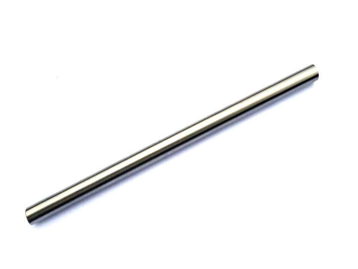
hollow shafts have a hollow inner cavity, which not only reduces the material consumption and overall weight of the shaft but also provides space for the integration of other components (such as cables, pipelines, and transmission shafts), realizing the miniaturization and integration of the mechanical system. However, the design of hollow shafts is more complex than that of solid shafts: the hollow structure will change the stress distribution of the shaft, requiring precise calculation of strength, rigidity, and fatigue life; the selection of materials and processing technology also directly affects the performance and reliability of hollow shafts. In practical applications, improper design of hollow shafts often leads to problems such as insufficient strength, poor rigidity, vibration, and premature failure, affecting the normal operation of the equipment.
Against this background, conducting in-depth research on the design points and application scenarios of hollow shafts is of great practical significance for promoting the standardized design and application of hollow shafts. This paper takes hollow shafts as the research object, systematically sorts out the key design considerations, analyzes the core application scenarios in various industries, and puts forward targeted design suggestions, providing professional technical support for the design, manufacturing, and application of hollow shafts. It is expected to help relevant practitioners avoid common design mistakes, improve the performance and reliability of hollow shafts, and further promote the upgrading and development of mechanical transmission technology.
2. Key Design Considerations of Hollow Shafts
The design of hollow shafts is a systematic project, which needs to comprehensively consider factors such as structural form, material performance, strength and rigidity calculation, processing technology, and sealing requirements. Each design link is closely linked, and any link that does not meet the requirements will affect the overall performance and service life of the hollow shaft. The following is a detailed elaboration of the key design considerations of hollow shafts.
2.1 Structural Design
The structural design of hollow shafts is the foundation of their performance, which mainly includes the determination of cross-sectional form, inner and outer diameter ratio, and structural details. The rational design of the structure can effectively improve the strength, rigidity, and transmission efficiency of the hollow shaft, while reducing weight and material consumption.
2.1.1 Cross-Section Form
The cross-sectional form of hollow shafts mainly includes circular, square, rectangular, and special-shaped cross-sections. Among them, circular cross-section is the most commonly used form, which has the advantages of uniform stress distribution, easy processing, and good rotation performance, suitable for most rotating transmission scenarios. Square and rectangular cross-sections are mainly used in non-rotating or low-speed transmission scenarios, such as linear guides and structural supports, which have the advantage of high torque transmission capacity in a certain direction. Special-shaped cross-sections (such as spline hollow shafts, keyway hollow shafts) are designed according to specific transmission requirements, realizing the integration of torque transmission and positioning functions.
2.1.2 Inner and Outer Diameter Ratio
The inner and outer diameter ratio (also known as the hollow ratio) is a key parameter affecting the performance of hollow shafts. The hollow ratio is usually expressed as the ratio of the inner diameter (d) to the outer diameter (D), i.e., α = d/D. The selection of the hollow ratio must balance the requirements of weight reduction, strength, and rigidity:
- When the hollow ratio is small (α < 0.5), the weight reduction effect of the hollow shaft is not obvious, and its performance is close to that of a solid shaft, which is suitable for scenarios where weight reduction requirements are not high but processing difficulty needs to be reduced.
- When the hollow ratio is moderate (0.5 ≤ α ≤ 0.8), the hollow shaft can achieve a good balance between weight reduction and performance. At this time, the weight of the hollow shaft is significantly reduced (compared with the solid shaft of the same outer diameter), while maintaining sufficient strength and rigidity, which is suitable for most industrial application scenarios.
- When the hollow ratio is large (α > 0.8), the weight reduction effect is significant, but the strength and rigidity of the hollow shaft will decrease sharply, and the shaft is prone to deformation and vibration under load, which is only suitable for light-load, low-speed, and non-critical transmission scenarios.
In practical design, the optimal hollow ratio is usually determined according to the working load, transmission speed, and weight reduction requirements, combined with strength and rigidity calculation.
2.1.3 Structural Details
The structural details of hollow shafts, such as the connection part with other components, the transition fillet, and the inner cavity surface, also need to be carefully designed to avoid stress concentration and improve the service life of the hollow shaft:
- Connection Part: The connection between the hollow shaft and gears, pulleys, or bearings usually adopts keyway connection, spline connection, or interference fit. The design of the connection part should ensure sufficient torque transmission capacity, and the keyway or spline should be reasonably arranged to avoid reducing the strength of the hollow shaft. For interference fit, the interference amount should be accurately calculated to ensure tight connection and avoid damage to the hollow shaft during assembly.
- Transition Fillet: The transition between the shaft shoulder and the shaft body, as well as between the inner and outer surfaces, should be designed with a reasonable fillet radius to avoid stress concentration. Stress concentration is the main cause of fatigue fracture of hollow shafts, and a proper fillet can effectively disperse stress and improve the fatigue life of the shaft.
- Inner Cavity Surface: The inner cavity surface of the hollow shaft should be smooth and free of burrs and defects to avoid stress concentration and reduce the resistance of the internal medium (such as lubricating oil, cables) passing through. For hollow shafts used in harsh environments, the inner cavity surface can be treated with anti-corrosion to improve corrosion resistance.
2.2 Material Selection
The material of hollow shafts directly determines their mechanical performance, wear resistance, corrosion resistance, and processing performance. The selection of materials must be based on the working environment, load requirements, transmission speed, and service life, comprehensively considering factors such as material performance, processing difficulty, and cost. Common materials for hollow shafts are as follows:
2.2.1 Carbon Steel
Carbon steel is the most commonly used material for hollow shafts in general scenarios, with the advantages of low cost, easy processing, and good mechanical properties. Common types include 45# steel, Q235 steel, and 20# steel:
- 45# Steel: A medium carbon steel with moderate tensile strength (≥600MPa) and yield strength (≥355MPa), good machinability and heat treatment performance. After quenching and tempering treatment, its strength and hardness can be further improved, and it is suitable for general medium-load, medium-speed transmission scenarios (such as industrial gearboxes, conveyor equipment).
- Q235 Steel: A low carbon steel with low strength (tensile strength ≥375MPa), good toughness and machinability, low cost. It is suitable for light-load, low-speed scenarios (such as small-scale conveyors, non-critical transmission components).
- 20# Steel: A low carbon steel with good plasticity and weldability, suitable for hollow shafts that need to be welded or have low strength requirements (such as auxiliary transmission shafts, light-duty mechanical components).
2.2.2 Alloy Steel
Alloy steel is added with alloying elements (such as chromium, nickel, molybdenum, manganese) on the basis of carbon steel, which has higher strength, hardness, wear resistance, and fatigue strength than carbon steel. It is suitable for high-load, high-speed, and harsh working environments:
- 40Cr Steel: A common alloy structural steel, containing chromium element, which has high tensile strength (≥980MPa), yield strength (≥785MPa), and good hardenability and wear resistance. After quenching and tempering treatment, it is widely used in high-load, medium-speed transmission scenarios (such as automotive drive shafts, heavy-duty gearboxes).
- 30CrMnTi Steel: A high-strength alloy steel, containing chromium, manganese, titanium elements, with high tensile strength (≥1180MPa), yield strength (≥835MPa), and excellent fatigue strength and wear resistance. It is suitable for high-load, high-frequency, high-precision transmission scenarios (such as aerospace transmission shafts, robot joints).
- 20CrMo Steel: A low-alloy steel, containing chromium and molybdenum elements, with good toughness, high-temperature resistance, and wear resistance. It is suitable for high-temperature, high-pressure transmission scenarios (such as engine crankshafts, high-temperature gearboxes).
2.2.3 Stainless Steel
Stainless steel has excellent corrosion resistance, wear resistance, and high-temperature resistance, and is suitable for hollow shafts working in corrosive, humid, and high-temperature environments. Common types include 304 stainless steel, 316 stainless steel, and 1Cr18Ni9Ti stainless steel:
- 304 Stainless Steel: Austenitic stainless steel, with good corrosion resistance, machinability, and toughness, suitable for general corrosive environments (such as chemical equipment, food processing machinery).
- 316 Stainless Steel: On the basis of 304 stainless steel, molybdenum element is added, which has better corrosion resistance (especially resistance to seawater and chemical media), and is suitable for harsh corrosive environments (such as marine equipment, chemical reaction vessels).
2.2.4 Non-Ferrous Alloys
Non-ferrous alloys are mainly used in special scenarios requiring lightweight, high corrosion resistance, and high precision, such as aerospace, medical equipment, and electric vehicles. Common types include aluminum alloy, titanium alloy, and copper alloy:
- Aluminum Alloy (6061, 7075): Lightweight (density 2.7g/cm³), good machinability and corrosion resistance, suitable for lightweight, low-load transmission scenarios (such as electric vehicle drive shafts, small aircraft components).
- Titanium Alloy (Ti-6Al-4V): A high-performance alloy with lightweight (density 4.5g/cm³), high strength (tensile strength ≥900MPa), excellent corrosion resistance, and high-temperature resistance. It is suitable for high-precision, high-reliability scenarios (such as aerospace hollow shafts, medical equipment).
2.3 Strength and Rigidity Calculation
Strength and rigidity are the core performance indicators of hollow shafts, which directly determine their ability to bear load and avoid deformation. The design of hollow shafts must go through strict strength and rigidity calculation to ensure that they can work stably under the maximum working load.
2.3.1 Strength Calculation
The strength calculation of hollow shafts mainly includes tensile strength, compressive strength, and fatigue strength calculation. For rotating hollow shafts, the most important is the torsion strength calculation, which is used to ensure that the hollow shaft does not fracture under the action of torque. The torsion strength calculation formula of a circular cross-section hollow shaft is as follows:
$$\tau_{max} = \frac{T \cdot D}{2 \cdot I_p} \leq [\tau]$$
Where: $$\tau_{max}$$ is the maximum shear stress (MPa); T is the torque acting on the hollow shaft (N·m); D is the outer diameter of the hollow shaft (m); $$I_p$$ is the polar moment of inertia (m⁴); $$[\tau]$$ is the allowable shear stress (MPa).
For hollow shafts bearing bending loads, bending strength calculation is also required to avoid bending deformation or fracture. The bending strength calculation formula is similar to that of solid shafts, but the moment of inertia needs to be calculated according to the hollow cross-section.
2.3.2 Rigidity Calculation
Rigidity calculation is used to ensure that the hollow shaft does not produce excessive deformation under the action of load, which affects the transmission accuracy and stability. The rigidity of hollow shafts mainly includes torsional rigidity and bending rigidity:
- Torsional Rigidity: The ability to resist torsional deformation. The torsional rigidity of a circular cross-section hollow shaft is expressed by the torsional stiffness coefficient $$G \cdot I_p$$, where G is the shear modulus of the material (MPa), and$$I_p$$ is the polar moment of inertia. The larger the torsional stiffness coefficient, the better the torsional rigidity.
- Bending Rigidity: The ability to resist bending deformation. The bending rigidity of a circular cross-section hollow shaft is expressed by the bending stiffness coefficient $$E \cdot I$$, where E is the elastic modulus of the material (MPa), and I is the moment of inertia of the cross-section. The larger the bending stiffness coefficient, the better the bending rigidity.
In practical design, the deformation of the hollow shaft under the maximum working load must be controlled within the allowable range to ensure the normal operation of the equipment.
2.4 Processing Technology
The processing technology of hollow shafts directly affects their dimensional accuracy, surface quality, and mechanical performance. The selection of processing technology must be based on the material, structural form, and precision requirements of the hollow shaft. Common processing technologies for hollow shafts include:
2.4.1 Seamless Pipe Processing
Seamless pipe processing is the most commonly used processing method for hollow shafts. It uses seamless steel pipes or seamless alloy pipes as blanks, and processes them into hollow shafts through turning, boring, grinding, and other processes. This method has the advantages of high production efficiency, low cost, and good dimensional accuracy, suitable for mass production of hollow shafts with circular cross-sections.
2.4.2 Forging Processing
Forging processing is suitable for hollow shafts with complex structures or high strength requirements. The blank is forged into a hollow shape through hot forging or cold forging, and then processed through turning, grinding, and other processes. Forging processing can improve the internal structure of the material, enhance the strength and toughness of the hollow shaft, and is suitable for high-load, high-reliability scenarios (such as automotive drive shafts, aerospace components).
2.4.3 Welding Processing
Welding processing is suitable for large-scale hollow shafts or hollow shafts with special structures. It uses steel plates or steel pipes to weld into a hollow structure, and then processes the surface and internal cavity. This method has the advantages of flexible design and low cost for large-scale components, but the welding quality must be strictly controlled to avoid welding defects (such as cracks, pores) that affect the strength of the hollow shaft.
2.4.4 Precision Machining
For hollow shafts with high precision requirements (such as high-precision gear shafts, robot joints), precision machining technologies such as CNC turning, CNC grinding, and honing are required to ensure the dimensional accuracy, surface roughness, and coaxiality of the hollow shaft. Precision machining can effectively improve the transmission accuracy and service life of the hollow shaft.
2.5 Sealing and Protection Design
For hollow shafts used in harsh environments (such as humid, dusty, corrosive environments), sealing and protection design is essential to prevent external dust, moisture, and chemical media from entering the inner cavity of the hollow shaft, avoiding corrosion and wear of the internal components and the hollow shaft itself. Common sealing and protection measures include:
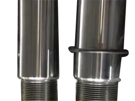
- Sealing Rings: Install sealing rings (such as O-rings, oil seals) at the ends of the hollow shaft or the connection part with other components to prevent the leakage of lubricating oil and the entry of external impurities.
- Protective Covers: Install protective covers on the outer surface of the hollow shaft to isolate it from the external environment, suitable for dusty, corrosive environments.
- Surface Treatment: Perform surface treatment (such as chrome plating, zinc plating, anodizing) on the outer and inner surfaces of the hollow shaft to improve corrosion resistance and wear resistance.
3. Core Application Scenarios of Hollow Shafts
Due to their advantages of lightweight, high rigidity, material saving, and integrated functional design, hollow shafts are widely used in various industries and scenarios, especially in scenarios requiring weight reduction, compact structure, and high transmission efficiency. The following is a detailed analysis of the core application scenarios of hollow shafts in various industries.
3.1 Industrial Machinery
Industrial machinery is one of the most important application fields of hollow shafts, mainly used in gearboxes, reducers, conveyors, and other equipment, undertaking the task of torque and power transmission.
- Gearboxes and Reducers: Hollow shafts are widely used in the input and output shafts of gearboxes and reducers. The hollow structure can reduce the weight of the shaft, improve the transmission efficiency, and provide space for the installation of other components (such as connecting shafts, cables). For example, in planetary gear reducers, hollow output shafts are often used to realize the integration of transmission and positioning, making the structure more compact.
- Conveyor Equipment: In belt conveyors, chain conveyors, and other equipment, hollow shafts are used as the driving shaft and driven shaft. The lightweight advantage of hollow shafts can reduce the load of the motor, save energy, and the hollow inner cavity can be used to pass through lubricating oil pipelines, facilitating lubrication and maintenance.
- Machine Tools: In CNC machine tools, machining centers, and other equipment, hollow shafts are used in the main shaft and feed shaft. The high rigidity and precision of hollow shafts ensure the machining accuracy of the machine tool, and the hollow inner cavity can be used to pass through the tool bar or workpiece, realizing the integration of processing and transmission.
3.2 Automotive Engineering
The automotive industry is a key application field of hollow shafts, which is in line with the development trend of automotive lightweight and energy conservation. Hollow shafts are mainly used in the drive system, suspension system, and engine components.
- Drive Shafts: The drive shaft of the automobile (especially the drive shaft of rear-wheel drive and four-wheel drive vehicles) usually adopts a hollow structure. Compared with the solid drive shaft, the hollow drive shaft can reduce the weight by 30%-50%, improve the fuel economy of the automobile, and at the same time maintain sufficient strength and torque transmission capacity. For example, the drive shafts of many high-end cars and new energy vehicles adopt hollow alloy steel shafts.
- Suspension System: In the automotive suspension system, hollow shafts are used in shock absorbers and control arms. The lightweight advantage of hollow shafts can reduce the unsprung mass of the automobile, improve the driving stability and comfort, and the good rigidity ensures the structural strength of the suspension system.
- Engine Components: In the automobile engine, hollow shafts are used in camshafts, crankshafts, and other components. The hollow structure can reduce the weight of the engine, improve the engine speed and efficiency, and the hollow inner cavity can be used to pass through the lubricating oil pipeline, ensuring the lubrication of the components.
3.3 Aerospace
In the aerospace field, the requirements for equipment lightweight, high reliability, and high precision are extremely high, and hollow shafts are widely used in aircraft engines, landing gear, and other components.
- Aircraft Engines: Hollow shafts are used in the rotor shafts, transmission shafts, and other components of aircraft engines. The lightweight advantage of hollow shafts can reduce the weight of the engine, improve the thrust-weight ratio of the aircraft, and the high strength and fatigue resistance ensure the reliable operation of the engine under high temperature and high pressure.
- Landing Gear: In the aircraft landing gear system, hollow shafts are used in the retraction mechanism and shock absorption mechanism. The lightweight and high rigidity of hollow shafts can reduce the weight of the landing gear, improve the landing safety of the aircraft, and the hollow inner cavity can be used to pass through the hydraulic pipeline and control cable.
- Satellite and Spacecraft: In satellites and spacecraft, hollow shafts are used in the attitude control system and transmission system. The lightweight and high precision of hollow shafts ensure the stability and accuracy of the spacecraft's attitude control, and the hollow structure can be used to integrate other functional components.
3.4 Robotics and Automation
With the rapid development of robotics and industrial automation, hollow shafts are widely used in robot joints, linear actuators, and other components, thanks to their compact structure and integrated functional design.
- Robot Joints: The joints of industrial robots and collaborative robots usually adopt hollow shafts. The hollow inner cavity can be used to pass through cables, hoses, and other components, realizing the integration of power transmission and signal transmission, making the robot joint structure more compact and flexible. At the same time, the lightweight advantage of hollow shafts can reduce the load of the robot arm, improve the movement speed and precision of the robot.
- Linear Actuators: In linear actuators (such as electric cylinders, hydraulic cylinders), hollow shafts are used as the push rod or transmission shaft. The hollow structure can be used to pass through the lead screw or hydraulic pipeline, realizing the miniaturization of the actuator, and the high rigidity ensures the push force and positioning accuracy of the actuator.
3.5 Other Application Scenarios
In addition to the above fields, hollow shafts are also used in other scenarios, such as:
- Medical Equipment: In medical robots, diagnostic equipment, and other medical devices, hollow shafts are used in the transmission and positioning mechanisms. The high precision and corrosion resistance of hollow shafts ensure the accuracy and reliability of medical equipment.
- Marine Equipment: In ships, offshore platforms, and other marine equipment, hollow shafts are used in the propeller shafts, transmission systems, and other components. The corrosion resistance of hollow shafts (after surface treatment) can adapt to the harsh marine environment, and the lightweight advantage can reduce the energy consumption of the ship.
- New Energy Equipment: In wind turbines, solar tracking systems, and other new energy equipment, hollow shafts are used in the transmission system. The high rigidity and fatigue resistance of hollow shafts ensure the stable operation of the equipment under harsh weather conditions, and the lightweight advantage can reduce the load of the equipment.
4. Common Design Challenges and Solution Strategies
In the design process of hollow shafts, due to the complexity of the hollow structure and the diversity of application scenarios, many design challenges are often encountered. The following are common design challenges and corresponding solution strategies:
4.1 Challenge 1: Insufficient Strength and Rigidity
Causes: Unreasonable selection of hollow ratio, improper material selection, or insufficient cross-sectional size, leading to insufficient strength and rigidity of the hollow shaft, which is prone to deformation or fracture under load.
Solution Strategies: Optimize the hollow ratio, select the appropriate inner and outer diameter ratio according to the load requirements; select high-strength materials (such as alloy steel) to improve the mechanical performance of the hollow shaft; increase the cross-sectional size of the hollow shaft or adopt a reinforced structure (such as ribbed hollow shaft) to enhance strength and rigidity.
4.2 Challenge 2: Stress Concentration
Causes: Unreasonable structural details (such as sharp corners, small fillet radius), improper connection design, leading to stress concentration at local positions of the hollow shaft, which is prone to fatigue fracture.
Solution Strategies: Optimize the structural details, increase the fillet radius at the transition position to disperse stress; reasonably design the connection part (such as keyway, spline), avoid reducing the local strength of the hollow shaft; perform surface treatment (such as shot peening) to improve the fatigue strength of the local position.
4.3 Challenge 3: Processing Difficulty and High Cost
Causes: Complex structural design, high precision requirements, or improper selection of processing technology, leading to high processing difficulty and cost.
Solution Strategies: Simplify the structural design on the premise of meeting performance requirements, avoid complex special-shaped structures; select appropriate processing technology according to the material and precision requirements (such as seamless pipe processing for mass production, forging processing for high-strength requirements); optimize the processing process to improve processing efficiency and reduce processing cost.
4.4 Challenge 4: Sealing and Corrosion Problems
Causes: Improper sealing design, insufficient surface treatment, leading to external impurities entering the inner cavity of the hollow shaft, or corrosion of the hollow shaft in harsh environments.
Solution Strategies: Optimize the sealing design, select appropriate sealing rings and protective covers to prevent the entry of external impurities; perform surface treatment (such as chrome plating, anodizing) on the inner and outer surfaces of the hollow shaft to improve corrosion resistance; regularly maintain and inspect the hollow shaft to timely replace damaged seals and repair corroded parts.
5. Development Trends of Hollow Shaft Technology
With the continuous advancement of material science, precision manufacturing technology, and intelligent manufacturing, hollow shaft technology is developing in the direction of high precision, high strength, lightweight, integration, and intelligence. The main development trends are as follows:
- High-Strength and Lightweight Material Application: New high-performance materials (such as high-strength alloy steel, composite materials, and titanium alloy) are continuously applied to hollow shafts, improving their strength and rigidity while further reducing weight, meeting the high-performance requirements of modern equipment.
- Precision and Intelligent Manufacturing: With the development of CNC machining, 3D printing, and other technologies, the processing precision of hollow shafts is continuously improved, and the intelligent manufacturing of hollow shafts is realized, including automatic processing, automatic inspection, and fault early warning, improving production efficiency and product quality.
- Integrated and Multi-Functional Design: The hollow shaft is integrated with other components (such as gears, bearings, sensors) to realize multi-functional integration, making the mechanical system more compact and efficient. For example, the integrated design of hollow shafts and sensors can realize real-time monitoring of the working status of the shaft.
- Green and Low-Carbon Development: By optimizing the design and selecting environmentally friendly materials, the material consumption and energy consumption of hollow shafts are reduced, and the recyclability of hollow shafts is improved, conforming to the concept of green and low-carbon development.
- Special Environment Adaptation: The development of hollow shafts suitable for special environments (such as ultra-high temperature, ultra-high pressure, ultra-corrosion) expands their application scope, meeting the needs of aerospace, marine, and other special fields.
6. Conclusion
Hollow shafts, as a high-performance mechanical transmission component, have unique advantages of lightweight, high rigidity, material saving, and integrated functional design, and have been widely applied in industrial machinery, automotive engineering, aerospace, robotics, and other fields. The rational design of hollow shafts is the key to ensuring their performance and reliability, which requires comprehensive consideration of structural design, material selection, strength and rigidity calculation, processing technology, and sealing protection. Each design link must be strictly controlled to avoid common design problems such as insufficient strength, stress concentration, and high processing cost.
The core application scenarios of hollow shafts are closely related to their structural advantages. In different industries and scenarios, the design of hollow shafts must be matched with the working requirements, load characteristics, and environmental conditions to give full play to their advantages. With the continuous advancement of technology, hollow shaft technology will develop towards high precision, high strength, lightweight, integration, and intelligence, and its application scope will be further expanded.
It is hoped that this paper can help relevant practitioners fully grasp the key design considerations and core application scenarios of hollow shafts, promote the standardized, rational, and efficient application of hollow shafts, and make greater contributions to the development of modern mechanical transmission technology towards high efficiency, stability, and intelligence.


 Home
News
Industry News
Hollow Shafts: Key Design Considerations And Core Application Scenarios Analysis
Home
News
Industry News
Hollow Shafts: Key Design Considerations And Core Application Scenarios Analysis 
 +86 13771119215