Introduction
A piston rod appears deceptively simple-a straight, round, chrome-plated steel bar. But manufacturing it correctly requires precise control of a multi-stage process where each step affects all subsequent steps. A material mismatch in stage one may not manifest as a failure until the rod is in service after chrome plating. Improper heat treatment causes dimensional distortion that ruins the precision grinding in subsequent stages. A grinding burn in stage four creates a crack-prone surface layer that leads to premature fatigue failure in service.
Understanding the manufacturing process is essential for anyone specifying, procuring, or manufacturing piston rods because it reveals where quality can be lost-and where inspection and controls are most critical.
This article walks through the complete manufacturing process for a standard hard chrome plated hydraulic piston rod, identifying the key quality parameters and defect modes at each stage.
Material Verification
Steel Bar Selection
Piston rods are manufactured from hot-rolled or cold-drawn steel bar stock, typically in the 20-80mm diameter range for standard industrial applications. The bar is purchased to specific steel grades with chemistry and mechanical properties defined in mill certificates.
Common steel grades and their applications:
|
Grade |
Application |
Tensile Strength (Q&T) |
Hardness (Q&T) |
|
CK45 (AISI 1045) |
Standard hydraulic cylinders |
600-750 MPa |
HRC22-28 |
|
42CrMo (AISI 4140) |
Heavy duty hydraulic cylinders |
750-900 MPa |
HRC28-35 |
|
38CrMoAlA |
Nitriding precision rods |
750-950 MPa |
HRC28-35 |
|
304/316L Stainless |
Corrosion-resistant applications |
480-720 MPa |
HB150-200 |
Material Verification Procedures
Mill certificate review: The steel bar supplier provides a mill certificate documenting:
Heat number and chemistry (heat analysis)
Mechanical properties from test specimens
Surface condition and dimensional tolerances
Incoming inspection verification:
Verify chemistry using optical emission spectrometer (OES) on a sample from each heat/lot
Verify mechanical properties if test certificates are questionable
Visual inspection for surface defects (seams, laps, cracks in the bar surface)
Dimensional verification of diameter and straightness
Critical note: A surface seam or lap in the bar stock will propagate as a crack through all subsequent machining and heat treatment. Any visible surface defect in the incoming bar should be cause for rejection.
Rough Machining
Turning Operations
The steel bar is mounted in a lathe or CNC turning center for rough machining. The objectives are:
Remove surface decarburization and bar surface defects
Machine the rod to a rough geometry with adequate machining allowance for finish machining
Machine features that require turning (flanges, grooves, rod end threads)
Typical machining allowance:
Diameter: 0.5-1.0mm per side (total 1.0-2.0mm diameter reduction)
Length: 2-5mm per end allowance for final cutting and facing
Critical parameter: The rough machining introduces significant residual stress into the surface layer from the cutting forces. This stress must be removed by stress relief heat treatment before finish machining.
Stress Introduction During Rough Machining
Cutting forces in machining create plastic deformation in the surface layer, resulting in compressive residual stress. When this compressed surface layer is subsequently machined off during finish grinding, the remaining stress in the rod is unbalanced, causing distortion.
Example: A rod rough turned to 50.5mm diameter will have compressive stress in the outer 0.5mm layer. When finish ground to 50.0mm, that compressed layer is removed. If stress relief is not performed, the now-unbalanced stress distribution causes the rod to bow as it seeks a new equilibrium shape.
Heat Treatment (Quenching and Tempering)
The Q&T Process
Quenching and tempering (Q&T) is the standard heat treatment for carbon and alloy steel piston rods. The process:
Austenitizing: Heat to 830-870 degrees C (depending on steel grade), holding long enough for the microstructure to fully transform to austenite
Quenching: Rapid cooling in water (carbon steel) or oil (alloy steel) to transform austenite to hard martensite
Tempering: Reheat to 550-680 degrees C (depending on target hardness), holding and cooling to reduce brittleness while maintaining adequate hardness
Why Q&T Is Required
The as-rolled or normalized steel bar has mechanical properties suitable for bar stock but inadequate for piston rod service. Q&T increases tensile strength by 50-100% over normalized condition:
CK45 normalized: approximately HRC15-20, tensile 550 MPa
CK45 Q&T: HRC22-28, tensile 600-750 MPa
The higher hardness and strength from Q&T is essential for:
Supporting the dynamic loads in hydraulic/pneumatic actuation
Providing adequate fatigue resistance for high-cycle loading
Supporting the chrome plating without plastic deformation under seal contact load
Common Heat Treatment Defects
Insufficient hardness (under-tempered or inadequate quench): Results in soft spots that wear rapidly under seal contact, causing premature cylinder failure.
Excessive hardness (untempered martensite): Results in brittle rod that cracks under impact or thermal shock. The rod must always be tempered after quenching.
Decarburization: Surface carbon loss during high-temperature austenitizing. The decarburized surface layer has lower hardness than the core and becomes the fatigue crack initiation site.
Distortion: Non-uniform cooling during quenching causes uneven transformation stresses, resulting in bent or warped rods. Requires straightening or re-machining.
Stress Relief and Finish Machining
Pre-Finish Stress Relief
After Q&T, the rod may require an additional stress relief heat treatment before finish machining if the Q&T distortion is significant or if the subsequent finish machining removes a substantial amount of material.
Standard practice: Stress relieve at 550-600 degrees C for 1-2 hours per 25mm section thickness. This does not significantly affect the Q&T hardness but redistributes residual machining and quenching stresses.
Multi-Stage Grinding Sequence
Finish machining of piston rods is performed exclusively by grinding (not turning) to achieve the required surface finish and dimensional accuracy.
Rough Grinding
Remove Q&T scale and achieve near-net diameter
Depth of cut: 0.1-0.3mm per pass
Coolant: High flow to prevent thermal damage
Target: Ra 1.6-3.2 micrometers, diameter within 0.05-0.10mm of final
Finish Grinding
Achieve final diameter and target surface roughness
Depth of cut: 0.01-0.05mm per pass
Spark-out passes: 3-5 additional passes without infeed to remove elastic deformation
Target: Ra 0.2-0.8 micrometers for standard rods; Ra 0.1-0.2 micrometers for precision rods
Thread Rolling or Cutting
Rod end connection threads are formed by rolling (preferred for fatigue strength) or cutting
Thread fit must be verified with thread plug/ring gauges
Grinding Defects
Grinding burn: Thermal damage from excessive heat input causes re-tempering of the martensitic surface layer. Detected by magnetic particle inspection (white spots indicate re-tempered zones). Causes 30-50% reduction in fatigue life.
Chatter marks: Periodic waviness on the surface from dynamic instability (wheel resonance, work speed issues). Causes increased seal wear.
Spiral lead: A systematic error where the rod has a helical rather than straight surface when rotated. Caused by wheel misalignment or workpiece vibration.
Hard Chrome Plating
Pre-Plating Preparation
The ground rod undergoes thorough cleaning before chrome plating:
Solvent degreasing: Remove machining oils and coolants
Alkaline cleaning: Remove any remaining organic contaminants
Acid activation: Hydrochloric acid immersion (10-20%) to remove surface oxides and create a active surface for coating adhesion
Rinsing: Multiple deionized water rinses between each step
Any contamination remaining on the surface at plating will cause poor adhesion and coating defects.
Chrome Plating Process
The electroplating process is described in detail in Article 01. For manufacturing process overview, the key points are:
Chromic acid/sulfuric acid bath at 50-60 degrees C
Current density 30-60 A/dm2
Deposition rate approximately 0.025-0.05mm per hour
Produces intentional microcrack network (greater than 2,000 cracks/cm)
Post-Plating Processing
After chrome plating, the rod may receive:
Grinding or polishing: To correct any thickness variation or achieve Ra 0.1-0.2 micrometers for precision applications
Seal area polishing: Light buffing of the seal contact zone to remove any plating roughness that would damage seals
Final Inspection
Inspection Parameters
|
Parameter |
Standard Tolerance |
Measurement Method |
|
Diameter |
IT6-IT8 |
Micrometer, air gauge |
|
Surface roughness |
Ra 0.2-0.8 micrometers |
Profilometer |
|
Surface hardness |
Per material spec |
Rockwell or Vickers |
|
Straightness |
0.03-0.05mm/m |
V-block + dial indicator |
|
Chrome thickness |
0.015-0.05mm |
Eddy current gauge |
|
Chrome adhesion |
No peeling or flaking |
Bend test or thermal shock |
|
Salt spray rating |
500+ hours |
Neutral salt spray test |
Traceability
Quality piston rod manufacturers maintain complete traceability:
Heat number and material certificate from steel bar
Heat treatment records (temperature, time, quench medium)
Grinding records (dates, operators, equipment)
Chrome plating records (bath chemistry, current density, thickness)
Inspection results with measurements
This traceability is essential for root cause analysis if a field failure occurs.
Key Takeaways
Piston rod manufacturing has 6 key stages: material verification, rough machining, Q&T heat treatment, stress relief + finish grinding, chrome plating, and final inspection; defects introduced in any stage propagate through subsequent stages
Quenching and tempering heat treatment increases CK45 steel from approximately HRC15-20 normalized to HRC22-28, providing the 600-750 MPa tensile strength required for hydraulic service; skipping or improperly performing Q&T is a primary cause of rod failure
Rough machining introduces compressive residual stress in the surface layer; if this layer is removed by finish grinding without intervening stress relief heat treatment, the rod will distort out of tolerance
Grinding burn (re-tempered martensite from excessive heat) is detected by magnetic particle inspection and causes 30-50% reduction in fatigue life; it is caused by dull wheels, inadequate coolant, or excessive depth of cut
Complete manufacturing traceability (heat number, process records, inspection data) is essential for quality assurance and root cause analysis when field failures occur
Conclusion
The
piston rod manufacturing process is a sequential discipline where each stage must be correctly executed for the subsequent stages to succeed. Attempting to shortcut or skip any stage-using incorrect material, skipping stress relief, inadequate heat treatment, or insufficient inspection-compromises the final product quality and causes failures that are expensive to investigate and resolve.
For engineering teams specifying piston rods, understanding this manufacturing process clarifies why certain requirements (material certificates, heat treatment specifications, inspection protocols) are not optional but are fundamental to ensuring the rod performs in service.
Wuxi Xinluo Hydraulic Machinery Co., Ltd. operates a complete in-house manufacturing facility for piston rods, with full material verification, heat treatment, grinding, chrome plating, and inspection capability under ISO 9001 quality control.









 Home
News
Industry News
Piston Rod Manufacturing Process: From Steel Bar To Chrome-Plated Precision Component
Home
News
Industry News
Piston Rod Manufacturing Process: From Steel Bar To Chrome-Plated Precision Component 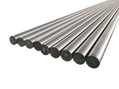

 +86 13771119215